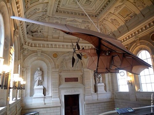
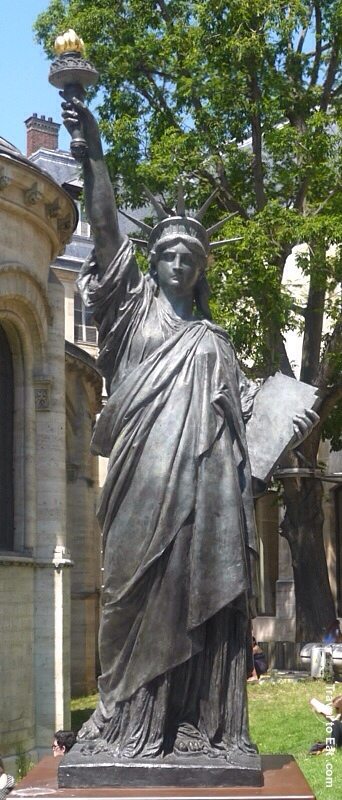
I wanted to write a little on the Musée des Arts et Métiers, a scientific museum like the Smithsonian, only smaller, in Paris. It was founded in 1794, during the French Revolution. It was first proposed by the abbot Henri Grégoire as a “depository for machines, models, tools, drawings, descriptions and books in all the areas of the arts and trades”. The deserted Priory of Saint-Martin-des-Champs was selected as the site of collection, which formally opened in 1802. It is a fun place for adults and children and has some really cool stuff in the collection. For instance, the airplane shown above was the original “bat-plane” created by Clément Ader, powered by a little steam engine of his own design. On 9 October 1890, Ader attempted a flight of the Éole. The aircraft took off, reaching a height of 20 cm, and flew for approximately 50 meters (160 ft), 13 years before the Wright Brothers. There are also some exhibits related to the statue of liberty including this 1/16 scale model at the entrance.
The Conservatoire National des Arts et Métiers (CNAM) is a doctoral degree-granting higher education program, operated by the French government, dedicated to providing education and conducting research for the promotion of science and industry. Some of the students were enjoying the sunny day.
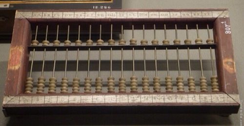
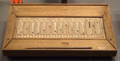
They have a collection of calculating machines. This is a Suan Pan (Mandarin for counting tray) Chinese Abacus from the 19th century. This one has the columns marked with a western alphabet, probably for teaching purposes. The Suan Pan, or Chinese abacus, had been in use in China for two or three centuries before making its journey to Japan sometime in the late 1500’s. Unlike the present day Japanese Soroban which has evolved to become an instrument with a 1/4 bead construction, the Suan Pan has retained its classic 2/5 bead construction – 2 beads above the reckoning bar, 5 beads below. These Suan Pans can be used for doing division, multiplication and for taking square roots and cube roots as well if the user knows the techniques. Chinese abacuses are designed to allow for hexadecimal computation. The Roman and Japanese versions are designed for base 10 computations although they are not directly related.
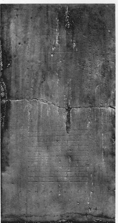
Before calculating devices, computations were either done in the head, on fingers, or by tallying. These sums were then noted in the sand or on flat surfaces covered with sand. Abaq or Abax stands for dust. Thus using the Abax or Abaq meant writing in dust. One of the earliest examples of permanent notation was recovered in 1854 near Babylon, called the Senkereh Tablet (Plimpton 322) which dates back to 2300-1600 BC. This may well have been a classroom exercise in mathematics that was inadvertently preserved. The earliest known counting board was discovered in 1899. The Salamis Tablet was found on the island of Salamis in Greece, dating back to 300 B.C. The tablet is marked at the top with a group of five small parallel lines chiseled onto the stone. Further down, towards the lower end of the tablet, are eleven longer parallel lines, a straight line runs down the center of the lower group. On the sides and bottom of the tablet are several Greek numerical and monetary denominational symbols. It is thought that the Greeks got this innovation from the Babylonians, transmitted it to the Romans who adapted it for their “hand abacus”. There is even a belief among some scholars that the Romans gave the idea to the Chinese along with their trade along the silk route.
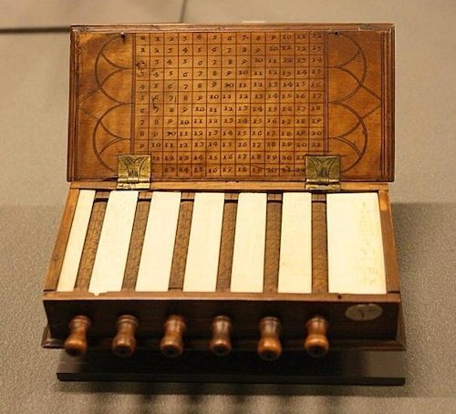
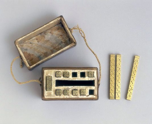
This instrument consists of a wooden box containing six rotating cylinders each of which bears the numbers ‘0 times’ to ‘9 times’. These sets would have been made to order for a wealthy client and regarded more as an adornment and status symbol than as tools for practitioners.
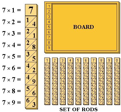
John Napier (1550-1617) is best known as the discoverer of logarithms. He was also the inventor of the so-called “Napier’s bones”. Napier also made common the use of the decimal point in arithmetic and mathematics. Napier’s bones is an abacus created by John Napier for calculation of products and quotients of numbers that was based on Arab mathematics and lattice multiplication used by Matrakci Nasuh in the Umdet-ul Hisab and Fibonacci writing in the Liber Abaci. Also called Rabdology (from Greek “rod” and “study”). Based on this concept, the English mathematician William Oughtred (1574-1660) invented the very useful “Slide Rule”.
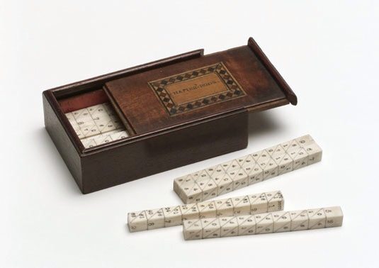
Napier published his version of rods in a work printed in Edinburgh, Scotland, at the end of 1617 entitled Rabdologiæ. Using the multiplication tables embedded in the rods, multiplication can be reduced to addition operations and division to subtractions. More advanced use of the rods can even extract square roots. Note that Napier’s bones are not the same as logarithms, with which Napier’s name is also associated. His work, Mirifici Logarithmorum Canonis Descriptio (1614) contained fifty-seven pages of explanatory matter and ninety pages of tables of numbers related to natural logarithms. He worked for more than twenty years to develop his theory and tables of what he called logarithms, a word he derived from two Greek roots: logos, meaning word, or study, or reasoning, or in Napier’s use, “reckoning”, and arithmos, meaning “number”. The book also has an excellent discussion of theorems in spherical trigonometry, usually known as Napier’s Rules of Circular Parts.
Riemannian geometry originated with the vision of Bernhard Riemann expressed in his inaugurational lecture “Ueber die Hypothesen, welche der Geometrie zu Grunde liegen” (On the hypotheses on which geometry is based). It is a very broad and abstract generalization of the differential geometry of surfaces in R3. Development of Riemannian geometry resulted in synthesis of diverse results concerning the geometry of surfaces and the behavior of geodesics on them, with techniques that can be applied to the study of differentiable manifolds of higher dimensions. It enabled Einstein’s general relativity theory, made profound impact on group theory and representation theory, as well as analysis, and spurred the development of algebraic and differential topology. (sorry about this last paragraph, just wanted you to know about the connection of non-Euclidian geometry and General Relativity … more in a separate post)

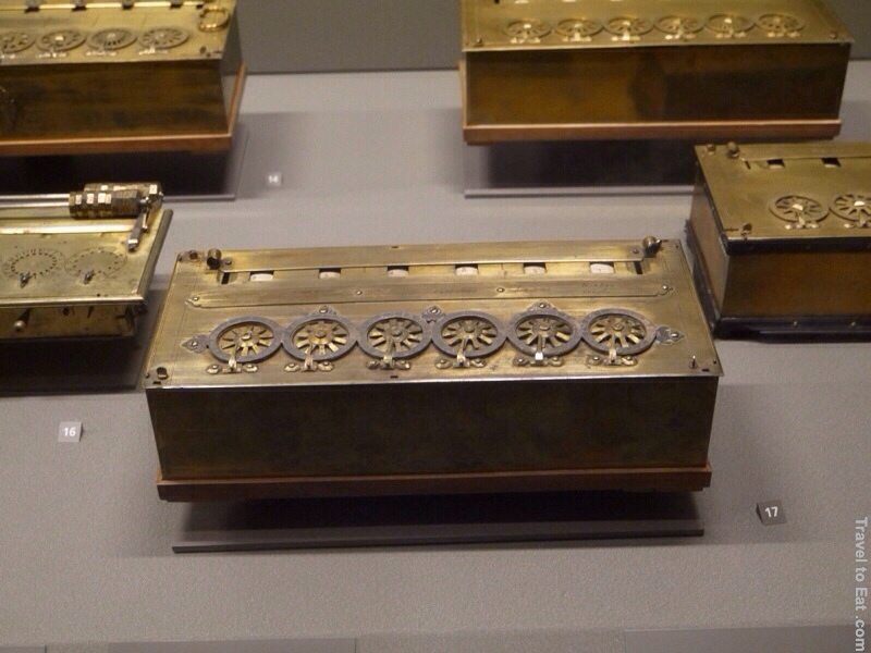
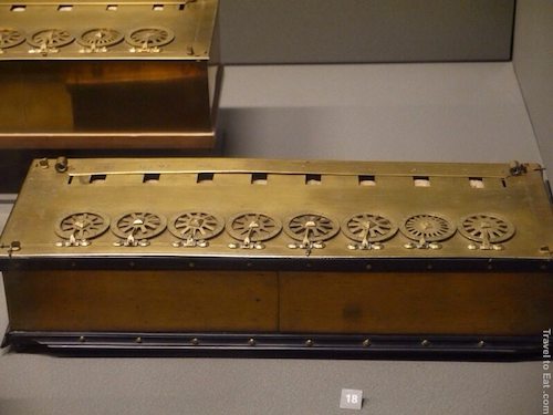
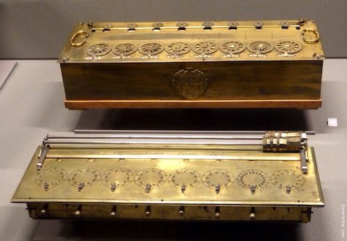
This is one of the two original six figure calculating machines by Blaise Pascal from 1642 signed by Pascal in 1652. In 1642, in an effort to ease his tax-collector father’s endless, exhausting calculations, and recalculations, of taxes owed and paid, Pascal, not yet nineteen, constructed a mechanical calculator capable of addition and subtraction (including the tens carry function) called Pascal’s calculator or the Pascaline. Because it was extraordinarily expensive the Pascaline became little more than a toy, and status symbol, for the very rich both in France and throughout Europe. However, Pascal continued to make improvements to his design through the next decade and built twenty machines in total (most must be in this collection). The little wheels only go in one direction due to the “chain”, a complex metallic part linking two decimal stages of the machine. With the help of this device, the carry is realized smoothly and successively, even in the case of an extensive carry digit. However, the operation of the chain is not reversible.
To understand this instrument, you first have to understand French money at the time. There were three basic denominations, the denier, the sou (12 deniers make one sou), and the livre (20 sous make one livre). The ratio of 12:20:1 is a classical one that supposedly reflected the relatives values of copper:silver:gold. Anywhere the Romans went, there are traces of a money system that uses these proportions. The English used a similar system where 12 pence = 1 shilling, 20 shillings = 1 pound sterling. The first instrument only added and subtracted livre. The one shown above, is a six figure Pascaline made in 1645, with two extra dials on the right for denier and sous. Notice that the six dials on the left have 10 spokes or positions, the second from the right has 20 (for sous) and the one to the far right has 12 (for denier). In about 1647 Pascal heard that a clockmaker in Roen was copying his machine. Pascal sent this machine to the Chancellor of France, Pierre Séguier, as a petition asking for protection of his invention. This one has a dedication inscribed to Chancellor Séguier.
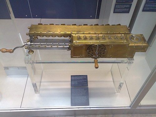
In 1672 Leibniz became acquainted with the calculating machine of Pascal (Pascaline), which he decided to improve. In the beginning of 1673, Leibniz was sent to London, where demonstrated the prototype of his calculating machine to the Royal Society. This was the first true four-function calculator (add, subtract, multiply and divide). His unique, drum-shaped gears formed the basis of mechanical calculators until electronic calculators were introduced. Leibniz built several versions of the Stepped Reckoner over about 45 years. Only 2 survive today, one in the Hanover State Library (it doesn’t work) and one in the Deutsches Museum in München.
This is an arithmetical machine by Caze from 1720. It consists of movable rulers (bars) with inscribed digits, which can be seen in windows. The upper row of windows (over the rulers) is used during adding operations, while the lower row (its digits actually are a complement to 10 of the digits in the upper windows) during subtraction. The device doesn’t have tens carry mechanism, you have to do it manually. In this sense it is really a sort of abacus. The columns are moved with the wooden stylus shown in the foreground. It does have two columns to the right for sous and deniers.
The calculator on the top of the above picture is another six figure Pascaline with sous and deniers but with little wheels above the numbers. Also there is a crest on the front. The bottom machine is a six figure addition and subtraction machine by Lepine from 1725. It seems to work on the same principles as the Pascaline but used a stylus to turn the dials and had a different internal mechanism. Apparently the carry mechanism, based on two springs, was not as reliable as Pascal’s. I don’t know what the drums on top were used for.
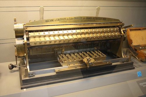
Léon Bollée (1870-1913) was a famous French inventor, auto manufacturer and racing enthusiast. Besides his passion for automobiles, Léon Bollée was obsessed by another passion, calculating machines and devices. The idea, used in the multiplying calculating machine of Bollée, is to use special bars with attached pins with different length, to be created something like a mechanical representation of the Napier’s bones. The different possible products are presented by means of two plates: first is for units, second is for tens. Bollée’s Multiplier won a gold medal at the 1889 Paris Exposition. Three versions of the large multiplier and several smaller machines were developed by Bollée and the devices were patented in France, Belgium, Germany, the USA and Hungary. Leon Bollee was the first person in France to create a small petrol car and so he called it “Voiturette”, distinguishing it from steam powered vehicles.
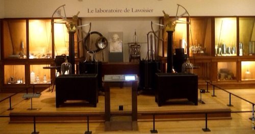
The museum has a whole room devoted to Antoine-Laurent Lavoisier, the father of modern chemistry. He spent a great deal of his time studying the physiology of respiration and the chemistry of combustion. Lavoisier’s work was greatly helped by the fact that the gases involved in respiration had already been identified and categorised by others. Joseph Black had isolated carbon dioxide (fixed air) in 1757; in 1766 Henry Cavendish had isolated hydrogen (incendiary air) while in 1772, Daniel Rutherford had isolated nitrogen (dead air). In the same year as Rutherford’s discovery, Joseph Priestly had isolated oxygen (fire air). His wife Marie-Anne actually learned English to help him translate these works and learned to draw with help from Jacques-Louis David. Lavoisier discovered the true nature of respiration when he found that it was a process whereby oxygen is taken up by blood in the lungs and expelled as carbon dioxide, much like the combustion of flammible materials. He also named hydrogen (Greek for “water-former”), oxygen (Greek for “becoming sharp”), described the composition of air as nitrogen and oxygen and the composition of water as hydrogen and oxygen (both were previously thought to be elements).
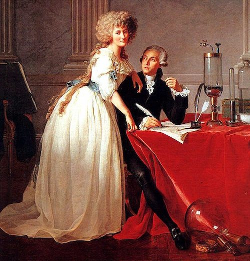
By carefully weighing everything using a chemical balance, Lavoisier discovered the law of conservation of mass and performed the first quantitative chemical experiments. Lavoisier devised a systematic chemical nomenclature, described in Méthode de nomenclature chimique (Method of Chemical Nomenclature, 1787). In 1661 Robert Boyle defined an element as a substance that cannot be broken down into a simpler substance by a chemical reaction. In his famous textbook, Traité Élémentaire de Chimie (Elementary Treatise of Chemistry, 1789). Lavoisier provided a list of elements including oxygen, nitrogen, hydrogen, phosphorus, mercury, zinc, and sulfur. This list forms the basis for the modern periodic table although light and caloric were also on the list. Although Lavoisier did not discover any new elements, he provided the framework for a new quantitative age of chemistry. The portrait of Lavoisier with his wife is ironic since Marat was responsible for the imprisonment of Lavoisier, died about a year before Lavoisier and the artist, Jacques-Louis David (who taught Marie-Anne to draw) is most famous for the painting “Death of Murat”.
Lavoisier took an active part in the French Revolution, and in its early years he promoted the establishment of the metric system of weights and measures. Unfortunately he, like many others died by the guillotine in 1794. Joseph-Louis Lagrange, remarked of this event, “It took them only an instant to cut off that head, and a hundred years may not produce another like it.”

The above room is devoted to Félix Savart who studied acoustics. He developed the Savart wheel which produces sound at specific graduated frequencies using rotating disks. Savart is the namesake of the unit of measurement for musical intervals, the savart.
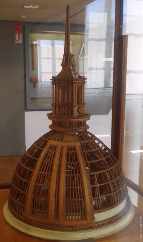
They have a section on architecture. This is a scale model from 1885 at 1/50th scale of the dome of Les Invalides. (see my post). Notice the double dome construction.
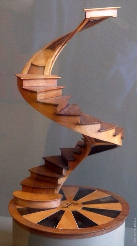
This is a cool model of a spiral staircase from 1830.
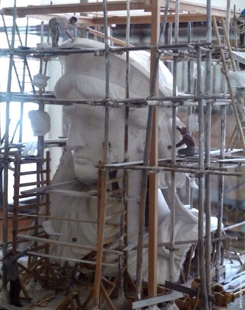
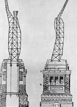
Several models of the work on the Statue of Liberty. The statue was created by pounding copper plates onto a model of the statue and suspending these plates on a steel armature built by Gustave Eiffel, seen to the right. The advantage of this design was that the statue could flex with the wind. Eiffel’s design made the statue one of the earliest examples of curtain wall construction, in which the exterior of the structure is not load bearing, but is instead supported by an interior framework.
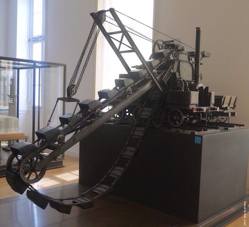
And a model of a big steam shovel.
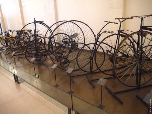
A large collection of antique bicycles.
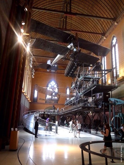
This is a view of the church of the old abbey, filled with airplanes, a steam engine and the original Foucault pendulum.
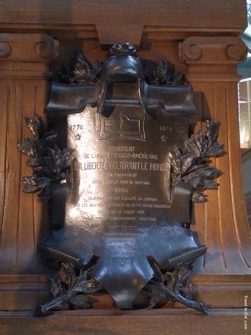
A copy of the plaque at the bottom of the Statue of Liberty.
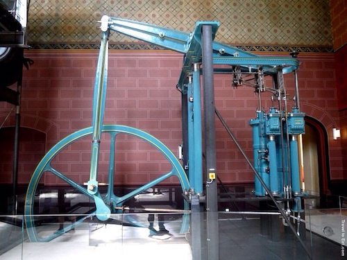
This is a two chamber steam beam engine made by a T Scott from Rouen in about 1860. Other than the two piston design, it is a faithful descendant of the Watt steam engine. It was disassembled in 1986 after being used in the Paris region for over a century, pumping water from the Seine. Who doesn’t like a huge gleaming steam engine?
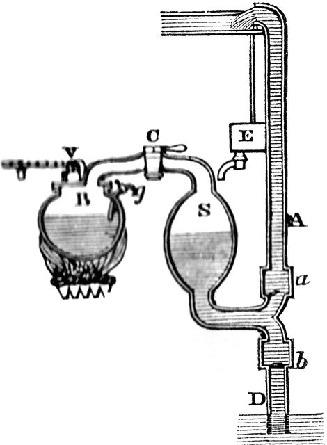
The original problem that was faced by developers of the steam engine was the problem of removing water from mines. The original solution was to use teams of horses to pull buckets up. In 1698 Thomas Savory patented a method to pump water out of mines. Savery’s engine had no piston, and no moving parts except for the valves. Basically he had a boiler B which created steam controlled by valve C which filled a vessel S. As the steam condensed, a vacuum was created which drew water into the vessel S. The steam was turned on again to drive the water up and out. It didn’t work, several blew apart.
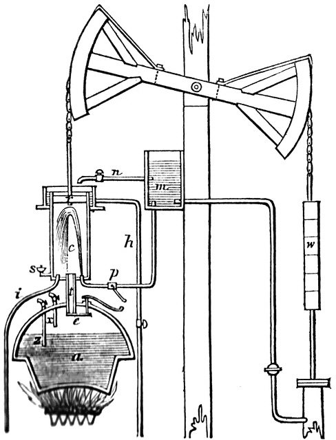
The next idea was the Newcomen engine from 1771, which had a piston but used a very similar principle. A weighted rocker arm drew the piston up. Low pressure steam went into the cylinder C and the valve was closed. A small amount of water was sprayed into the chamber to condense the steam which created a vacuum, drawing the piston downward. The beam was rotated via a chain and water was pumped upwards. The pump itself was similar to a simple hand pump. A system of valves made the process self repeating. This engine was a great success for almost 50 years.
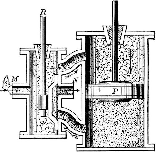
A Scottish instrument maker, James Watt, was given the job in 1763 of repairing a model Newcomen engine for the University of Glasgow, and noted how inefficient it was. The chamber was cooled every time water was sprayed in, requiring more heat to fill it with steam again. Watt made a separate chamber to cool the steam and made the piston do double duty, filling one side with steam while the other condensed and vice-versa. Even though the steam was only 2-3 psi it made a huge difference in efficiency. The truth is, if he had better high pressure boilers, he could have just vented the steam, the main improvement was to use the power of steam to push rather than just create a vacuum to pull the piston. After the patent expired, Cornish engineers did just that, using higher pressure steam to drive the piston. So with this background lets examine this low pressure Watt beam steam engine.
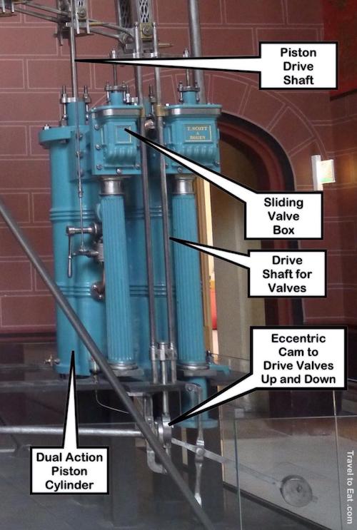
Here we see two sets of pistons and condensation tanks with the sliding valve box shown above. The condensation chambers are not shown, usually they were submerged in water. Watts originally had trouble getting a perfectly round bore for the piston chambers. In 1774 John Wilkinson invented a boring machine in which the shaft that held the cutting tool was supported on both ends and extended through the cylinder, unlike the cantilevered borers then in use, making much more even bores.
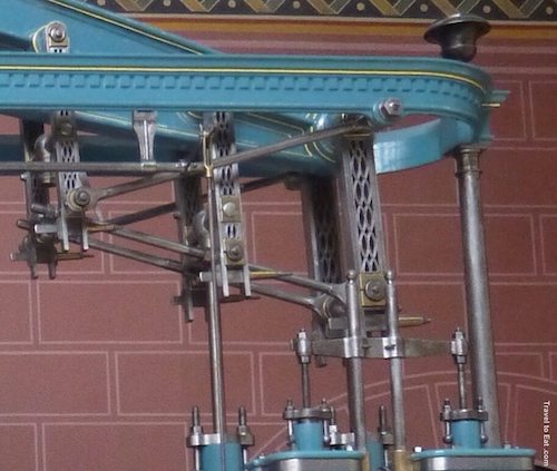
Here we see the parallelogram linkage that Watt was so proud of. Since the piston rods go straight up and down, while the end of the beam goes along an arc, a linkage was needed to connect the two. The chain used on the Newcomen engine wouldn’t work since the engine is now pushing as well as pulling the beam, so Watt came up with this ingenious solution.
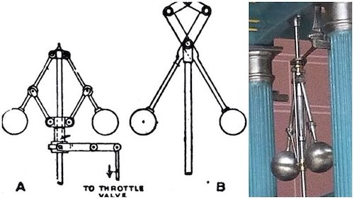
The huge wheel was used as a “fly wheel” which smoothed the action of the alternating strokes. To its rotating central shaft, belts and gears could be attached to drive different kinds of machinery in addition to pumps. In the picture above we see the Watt governer which helped keep the speed of the engine constant. It was attached by linkages to the input steam valve, providing more or less steam as required.
The Watt engine began the industrial revolution which exchanged horses and water wheels as a source of power for manufacturing. The principles developed here eventually led to giant steam shovels like the one shown above and the steam locomotive, paving the way for a new way of life for the world.
References:
Musée des Arts et Métiers: http://www.arts-et-metiers.net/?lang=ang
Chinese Abacus: http://www.alcula.com/suanpan.php
How to use a Chinese Abacus: http://webhome.idirect.com/~totton/abacus/pages.htm
Napier’s bones: http://en.wikipedia.org/wiki/Napier%27s_bones
Science Museum, London: http://www.sciencemuseum.org.uk/