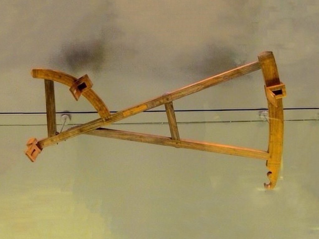

They have a nice collection of navigational instruments at the French Maritime Museum, so I thought I would share some with you. The little gadget shown above is called a ship log, and it is a way of determining the speed of the boat through water. This is the evolved form of throwing a chip of wood overboard and seeing how far it goes in a few seconds. In the above picture you can see a thirty second sandglass. The idea is to throw it overboard, let it float there for 30 seconds, while the ship moves away. The line has knots on it every so often and thus you can measure the speed of the boat.

In navigation, dead reckoning is the process of calculating one's current position by using a previously determined position, or fix, and advancing that position based upon known or estimated speeds over elapsed time, and course (direction). So in the diagram above, if you want to go from the green island to the red one, and you can always see it, you just point the boat and go. However, if you want to go to the blue island, 4 times as far away, and you cannot see it, you can just point the boat in the right direction and go. If the trip takes more than 4 times as long, you missed the island and you are lost! The only four things you need to know about navigation are speed, time, position and direction. All navigation instruments tell you one or more of those four variables. Wind and currents are additional things that can foul up dead reckoning and the farther you go, the more inaccurate the result.

Direction is obviously an important thing thing to know and you might wonder how people got around before the compass. Prior to the Phoenician discovery of how to use Polaris, ships traveling on the Mediterranean Sea tended to stay within view of the coastline to avoid getting lost, even if this made the course to their destination extremely indirect. Once navigators realized that they could keep Polaris directly in front or in back of their ship at night, ships began crossing the Mediterranean along direct north-south routes. Now possible were fast trips between Africa and points across the sea such as Cyprus, Anatolia, Greece, Crete, and Italy.
The Phoenicians built up a store of information about winds and currents, which they guarded jealously as valuable trade secrets. The pharaoh Necho II sent a fleet of Phoenician ships south through the Red Sea to discover whether Africa is entirely surrounded by water in 600 BC. Their achievement of this astonishing feat of exploration might easily be assigned to the realms of legend. But Herodotus, in his account, mentions one detail which he dismisses as highly improbable. Instead, it proves the story true. He says that the sailors, when they came back, claimed that during the furthest part of their journey they saw the sun to the north of them indicating they had gone past the equator. They also discovered the Canary Islands from which Columbus left for the new world.

Before the 19th-century development of the marine chronometer and the lunar distance method, dead reckoning was the primary method of determining longitude available to mariners such as Christopher Columbus and John Cabot on their trans-Atlantic voyages. The Vikings also used dead reckoning although they really did not use time or speed except for perhaps days sailed. Sailing east or west along a given lattitude is the easiest type of long distance sea travel. As long as you keep the north star at a given height above the horizon, you will go due east or west. To get to a given place like Greenland or Iceland, just go up or down the coast of Norway and go due east.


To keep track of their lattitude during the day, the Vikings used a sunboard, a sundial with a hyperbola inscribed for the path of the sun's shadow at a given time of year. If the shadow is too long, go south, too short, go north.

The magnetic compass is an old Chinese invention, probably first made in China during the Qin dynasty (221-206 B.C.). By the 11th Century, floating or water-compasses guided Chinese ships. The typical Chinese navigational compass was in the form of a magnetic needle or fish floating in a bowl of water. One hundred years later, these magnetic compasses were used aboard European ships. As noted in Voyagers, Columbus used a magnetic compass on his first trans-Atlantic trip. Columbus discovered, through his compass sightings, that the North Star (Polaris) was not exactly due north. In 1492, Polaris was off by about 3.5 degrees which caused it to circle the sky like every other star. The Chinese compass shown above is in the French Maritime Museum probably from the 18th century. The European compass-card in box frame and dry pivot needle was adopted in China after its use was taken by Japanese pirates in the 16th century (who had in turn learned of it from Europeans).


The dry mariner's compass was invented in Europe around 1300. The Portugese compass shown above from 1744 is unique for it's wind rose card. Note that the compass is mounted on gimbals to account for pitch and roll of the ship. The more traditional compass rose face is seen to the left in a compass by Joseph Roux from 1743. Each of these cards has a magnet glued to the bottom.
In the Mediterranean, the introduction of the compass, at first only known as a magnetized pointer floating in a bowl of water, went hand in hand with improvements in dead reckoning methods, and the development of Portolan charts, leading to more navigation during winter months in the second half of the 13th century. While the practice from ancient times had been to curtail sea travel between October and April, due in part to the lack of dependable clear skies during the Mediterranean winter, the prolongation of the sailing season resulted in a gradual, but sustained increase in shipping movement; by around 1290 the sailing season could start in late January or February, and end in December. The additional few months were of considerable economic importance. For instance, it enabled Venetian convoys to make two round trips a year to the Levant, instead of one.

A view of the compass collection at the French Maritime Museum.

The elevation of the north star depends on your lattitude. For instance, if Polaris is 10 degrees above the horizon, then you are 10 degrees from the equator in lattitude. A finger is about 1.36 degrees at arms length. Not very accurate so the Arabs came up with the Kamal, a little piece of string attached to a small piece of wood. Before leaving homeport, the navigator would tie a knot in the cord so that, by holding it in his teeth or touching to his nose he could sight Polaris along the top of the wood and the horizon along the bottom. To return to homeport, he would sail north or south as needed to bring Polaris to the altitude he had observed when he left home, then sail down the latitude. Over time, Arab navigators started tying knots in the string at intervals of one issabah. The word issabah is Arabic for finger, and it denotes one degree 36 minutes, which was considered to be the width of a finger. They even developed a journal of different ports that recorded which knot on the kamal corresponded to the altitude of Polaris for each port they frequently visited.


The next step in the evolution of celestial navigation instruments was the arbalete or cross-staff, a device resembling a Christian cross. Interestingly, its operating principle was the same as that of the kamal. The vertical piece, the transom or limb, slides along the staff so that the star can be sighted over the upper edge of the transom while the horizon is aligned with the bottom edge. Early cross-staffs had only two pieces – the staff and one transom (cross piece). Over time they became more elaborate. After 1650, most “modern” cross-staffs have four transoms of varying lengths. Each transom corresponds to the scale on one of the four sides of the staff. These scales mark off 90, 60, 30, and 10 degrees, respectively. In practice, the navigator used only one transom at a time.


The “Davis Quadrent or Backstaff” seen above was made in the 18th century by R. Merchant (Musée des arts et métiers). In this instrument, the observer determines the altitude of the sun by observing its shadow while simultaneously sighting the horizon. The major problem with back-sight instruments was that it was difficult if not impossible to sight the moon, the planets or the stars.

Sir Isaac Newton invented the principle of the doubly reflecting navigation instrument, but never published it. Two men independently developed the octant around 1730: John Hadley, an English mathematician, and Thomas Godfrey, a glazier in Philadelphia. The octant and later the sextant, replaced the Davis quadrant as the main instrument for navigation. The picture above shows a Hadley Octant from 1730 made by the famous London maker George Adams (Musée des arts et métiers, Paris). Hadley's first doubly reflecting octants were made from solid sheets of brass. They were heavy and had a lot of wind resistance. Lighter wooden instruments that could be made larger, with scales easier to divide accurately and with less wind resistance quickly replaced them. As you can see, the two mirrors reflect the sun (yellow arrows) to the pinhole, while the observer looks straight ahead (red arrow) at the horizon.


The instrument shown above is made of ebony with ivory inlays for the scales signed 1761. It is much lighter and has filters added to block out the brightness of the sun. The earliest mirrors were polished metal, since the technology to produce silvered glass mirrors with flat, parallel surfaces was limited. As glass polishing techniques improved, glass mirrors began to be provided. These used coatings of mercury-containing tin amalgam; coatings of silver or aluminum were not available until the 19th century. The poor optical quality of the early polished speculum metal mirrors meant that telescopic sights were not practical. For that reason, most early octants employed a simple naked-eye sighting pinnula instead. Octants were produced in large numbers. In wood and ivory, their relatively low price compared to an all-brass sextant made them a popular instrument. The design was standardized with many manufacturers using the identical frame style and components.

An octant measures angles up to 90 degrees and is ideally suited for observations of celestial bodies above the horizon. But greater angle range is needed for lunar distance observations. It was a simple matter to enlarge Hadley's octant, an eighth of a circle, to the sextant, a sixth of a circle, that could measure up to 120 degrees. John Bird made the first sextant in 1757. The wooden sextant seen above is from 1774 made by Edward Nairne, London (French Maritime Museum).

This is a Ramsden sextant from the the late 18th century (Musée des arts et métiers). Jesse Ramsden (1735-1800) had the justifiable reputation, in his own lifetime, of being London’s finest scientific instrument maker. Duc de Chaulnes created two dividing engines between 1765 and 1768 for dividing circular arcs and linear scales. Jesse Ramsden followed duc de Chaulnes by five years in the production of his dividing engine. As with the prior inventions, Ramsden's used a tangent screw mechanism to advance the machine from one position to another. However, he had developed a screw-cutting lathe that was particularly advanced and produced a superior product.
It is said that Ramsden first had his attention drawn to the subject of dividing engines in 1760 by the reward which was presented by the Board of Longitude to John Bird for his method of dividing. Ramsden made his first engine by 1768 but although it proved better than the results achieved by the ordinary dividing plate method it was not accurate enough for astronomical instruments. However by June 1774 he had completed his second engine and had presented a memorial to the Board of Longitude. By May 1775 the Board had sought John Bird's opinion and he reported that he had found the divisions of the scale of a Hadley sextant divided by the new engine “…extremely exact…” In France, Étienne Lenoir created a dividing engine of greater accuracy than the English version. Mégnié, Richer, Fortin and Jecker had also built dividing engines of considerable quality.


The double frame sextant shown above is from 1835 made by the famous Duncan McGregor & Co. A sextant is used in celestial navigation to determine longitude and lattitude. It measures the angle of an object like the moon, sun or north star above the horizon. Edward Troughton patented the double-framed sextant in 1788. This used two frames held in parallel with spacers or pillars. The two frames were about a centimetre apart. This significantly increased the stiffness of the frame while reducing weight. These are sometimes called “pillar” sextants.
The little animation above from Wikipedia, shows how a sextant works by splitting the view of the horizon and the sun, allowing a very accurate reading of the angle of the sun above the horizon. The sextant really improved the accuracy of reading angles between things, particularly between the horizon and the north star Polaris, the sun and the moon.

If you can measure the angle between the north star and the horizon, you can tell what lattitude (horizontal lines on the globe to the left) you are at. For instance, if Polaris is 10 degrees above the horizon, then you are 10 degrees from the equator in lattitude.
The purpose of a chronometer is to measure accurately the time of a known fixed location, for example Greenwich Mean Time (GMT). This is particularly important for navigation. Knowing GMT at local noon allows a navigator to use the time difference between the ship's position and the Greenwich Meridian to determine the ship's longitude (vertical lines on the globe). We all know that local time changes as we travel east or west as compared to home, and this method is just a refinement of that knowlege.

In 1714, the British government offered a longitude prize for a method of determining longitude at sea. A suitable timepiece was eventually built by John Harrison, in 1735. Harrison eventually built five chronometers, two of which were tested at sea. Though the British Parliament rewarded John Harrison for his marine chronometer in 1773, his chronometers were not to become standard. Seen above is the H1 (1735), H4 (1761) and H5 (1772). Captain James Cook used K1, a copy of H4, on his second and third voyages.


Ferdinand Berthoud in France, as well as Thomas Mudge in Britain also successfully produced marine timekeepers, showing that there were different solutions than just Harrison's. The chronometer shown above is by Berthoud no. 2, 1763 from the Musée des Arts et Métiers. Initially, the cost of these chronometers was quite high (roughly 30% of a ship's cost) and they were not used on all ships. However, by 1825 all British ships had chronometers, due mostly to John Arnold and Thomas Ernshaw. It can be said that, from around 1770, Arnold continued the development of portable precision timekeepers almost from the point at which the development of John Harrison's precision timekeeper had ended. The chronometer seen to the right is by Ferdinand Berthoud no. 3, 1763 from the Musée des Arts et Métiers. It is bigger than it looks in the picture, about 6″ in diameter. The French are quite right to point to Ferdinand Berthoud and Pierre LeRoy as co-inventors of the marine chronometer with John Harrison.

About the same time in France, Pierre Le Roy invented in 1748 the detent escapement characteristic of modern chronometers. In 1766, Pierre Le Roy created a revolutionary chronometer seen above at the Musée des Arts et Métiers. The innovations of Le Roy made the chronometer a much more accurate piece than had been anticipated by Newton and others.

In 1815, after the introduction of his marine chronometers among other achievements, King Louis XVIII of France awarded Abraham-Louis Breguet (1747-1823) the prestigious title of Horologer (clockmaker) to the French Royal Navy. He was a member of the French Board of Longitude, a body set up to assess the quality of timekeepers made to find longitude, and was also a member of the French Royal Academy. The “dual barrel” chronometer seen to the left was completed in 1813 and used as an experimental piece by Breguet himself until 1822. (British Museum)

The “double barrel” chronometer shown above from the Musee Maritime, and pioneered by Abraham-Louis Breguet, was built in the nineteenth century by his son, Antoine-Louis Breguet. It was built between 1823 and 1833. Note that it is mounted on gimbals to keep it level as the ship rolls and pitches and was meant to be sealed in a box. Alongside his friend and contemporary John Arnold, Breguet is now widely acknowledged as one of the greatest horologists (clockmakers) of all time.

Legend has it that it was the ill-fated French queen herself who commissioned Breguet's masterpiece, the “Marie Antoinette” (No. 160), which is now widely regarded as one of the most important and valuable timepieces ever made. Begun in 1783, it was not until 1827 that it was completed. It is a “perpetual watch with a minute repeater, a full perpetual calendar, an equation of time, a power reserve indicator, a metal thermometer, a large independent seconds hand and a small direct-drive seconds hand, a lever escapement, a gold balance spring, an anti-shock device, the points of friction, holes and bearings all set in sapphire, housed inside a gold case, with a rock crystal dial and gold and steel hands.” In 1983 this watch was valued at over 30 million dollars.

John Arnold (1736-1799) was the first to design a watch that was both practical and accurate, and also brought the term “Chronometer” in to use in its modern sense, meaning a precision timekeeper. His technical advances along with Thomas Earnshaw enabled the quantity production of Marine Chronometers for use on board British ships from around 1782. The Arnold chronometers shown above were both made in 1771 and used on Cooks second voyage to the South Pacific. Between 1800 and 1850 (earlier in British and French navigation practice, later in American, Russian, and other maritime countries), affordable, reliable marine chronometers became available. The basic design of these, with a few modifications remained unchanged until the late twentieth century. One can say that both John Arnold and Abraham-Louis Breguet largely invented the modern mechanical watch. When Arnold died, Breguet gave the the son the watch below, inscribed – 'The first tourbillon regulator by Breguet incorporated in one of the first works of Arnold. Breguet's homage to the revered memory of Arnold. Presented to his son in 1808'. (British Museum)

Traditionally, chronometers were kept in a dry room near the centre of the ship ( the most stable place on the ship). They were used to set a watch for the actual sight, so that no chronometers were ever exposed to the wind and salt water on deck. Winding and comparing the chronometers was a crucial duty of the navigator. Even today, it is still logged daily in the ship's deck log and reported to the Captain prior to eight bells on the forenoon watch (shipboard noon). Navigators also set the ship's clocks and calendar.

Without their accuracy and the accuracy of the feats of navigation that marine chronometers enabled, it is quite likely the ascendancy of the Royal Navy, and by extension that of the British Empire, would not have occurred; the formation of the empire by wars and conquests of colonies abroad took place in a period in which British vessels had reliable navigation due to the chronometer, while their Portuguese, Spanish and Dutch opponents did not. The French had reliable chronometers but the revolutions that occurred throughout the 19th century and poor military decisions hampered their overseas holdings.
Modern sailors have a number of choices for determining accurate positional information, including radar and the Global Positioning System, commonly known as GPS, a satellite navigation system. Even with the availability of multiple modern methods of determining longitude, a marine chronometer and sextant are routinely carried as a backup system.
As a navigation instrument, the reflecting circle was more popular with the French navy than with the British. The principles of operation are similar.

The reflecting circle was invented by the German geometer and astronomer Tobias Mayer in 1752, with details published in 1767. His development preceded the sextant and was motivated by the need to create a superior surveying instrument. In the field however, it was heavy and hard to use, in Britain the sextant won out. Jean-Charles de Borda further developed the reflecting circle and presented it in 1777. This instrument was so distinctive it was given the name Borda circle seen above from 1795, signed Jecker a Paris #6.

Josef de Mendoza y Ríos redesigned Borda's reflecting circle (London, 1801). The goal was to use it together with his Lunar Tables published by the Royal Society (London, 1805). The instrument shown above is from 1810, signed Troughton, London, Capt Mendoza invt.
Edward Troughton (inventor of the double frame sextant), also modified the reflecting circle. He created a design with three index arms and verniers. This permitted three simultaneous readings to average out the error.

Jules Sébastien César Dumont d'Urville (1790–1842) was a French explorer, naval officer and rear admiral, who explored the south and western Pacific, Australia, New Zealand and Antarctica. As a botanist and cartographer he left his mark, giving his name to several seaweeds, plants and shrubs, and places such as D'Urville Island. The Borda Circle seen above is from 1810, signed Jecker a Paris # 134 and was used on Dumont d'Urville's explorations in the south Pacific.